


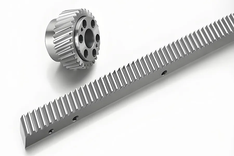
In gear rack design, many beginners focus on a few parameters such as “module and number of teeth,” but in actual engineering, these are far from sufficient. Whether a gear can be correctly manufactured, smoothly assembled, and reliably operated for a long time depends on the completeness of the parameters and the thoroughness of the evaluation. This article mainly introduces the basic parameters of gear racks.
1. Parameters
To completely define a gear, the basic parameters we need to specify include the number of teeth, normal module, normal pressure angle, helix angle, tooth width, addendum circle diameter, dedendum circle diameter, number of teeth spanned, common normal length (the number of teeth spanned and common normal length can be directly replaced by measuring rod and span distance), and center distance. You might be wondering why there is no modification coefficient? Below, we will introduce the meaning of each parameter.
2. Number of Teeth
Symbol Z, the total number of teeth on the entire circumference of the gear rack.
3. Module
Normal module, symbol mn. Besides the normal module, there is also the end-face module, symbol mt. In spur gear racks, the normal module and end-face module are equal, while in helical gears, their relationship is:
mt = mn / cosβ, where β is the gear helix angle.
The normal module refers to the module of the tool used to machine the gear, and its plane is perpendicular to the helix angle generatrix. The end-face module refers to the module of the gear rack on a plane parallel to the end face of the gear.
The module m itself has no physical meaning; its function is to replace the gear pitch P: P = πm
Once the module m is determined, the thickness of a single tooth of the gear is basically determined, and combined with the number of teeth Z, the size of a gear is basically determined. The module m affects the gear strength; fracture and wear can be improved by increasing the module.
4. Normal Pressure Angle
Symbol αn. The pressure angle is the angle between the direction of involute motion and the direction of force. The pressure angle at each point on the involute is different; the further away from the base circle, the larger the pressure angle. The pressure angle at the base circle is 0°, and in most countries in the world, the pressure angle at the pitch circle is 20°. There’s a concept everyone needs to understand: the pressure angle is different at different points on the gear rack. Therefore, some people say that changing the pressure angle can change the contact ratio, strength, etc., which is correct.
Adjusting the modification coefficient optimizes gear transmission.
However, the principle is to optimize gear transmission by adjusting the shape of the involute curve. Generally, we can achieve the same effect by adjusting the modification coefficient. Adjusting the pressure angle requires changing the cutting tool, while the modification coefficient can be adjusted simply by adjusting the tool position. Therefore, under normal circumstances, we can achieve gear optimization by adjusting the modification coefficient. Only when it’s impossible to adjust through the modification coefficient do we adjust the pressure angle. This is because changing the pressure angle requires ordering a new cutting tool, which is time-consuming and expensive.
5. Helix Angle
Symbol β, the acute angle between the tangent of the helical line on the pitch cylinder of a helical gear rack and its axis is called the pitch cylinder helix angle, or simply the helix angle.
The advantage of helical gears over spur gears is that helical gears have a larger contact ratio, which improves both gear strength and smoothness. Therefore, helical gears are suitable for higher speeds under the same machining accuracy.
The helix angle of a spur gear is 0. Of course, the disadvantage of helical gears is that meshing generates axial forces, and the axial positioning requirements of helical gears are much higher than those of spur gears.
6. Tooth Width
Symbol b, the width of the toothed part of the gear rack measured along the straight generatrix direction of the pitch cylinder.
The size of the tooth width affects the contact ratio of the helical gear, and also affects the gear strength because it influences the contact area. Ideally, the longer the tooth width, the greater the increase in strength. However, in reality, due to machining errors, the longer the tooth width, the greater the error, leading to increased meshing impact and thus reduced gear strength. Therefore, selecting an appropriate tooth width is very necessary; the idea that longer tooth width always means better strength is incorrect.
7. Addendum Circle
Symbol da, the circle passing through the tips of the gear rack teeth. Its diameter is represented by da, and its radius by ra. The addendum circle is very important in gear parameters; its value affects the contact ratio, sliding rate, tooth tip thickness, etc., and improper values can even cause gear meshing interference.
8. Root Circle
The root circle, denoted by df, is the circle tangent to the bottom of the tooth spaces of all the gear rack teeth. Its diameter is denoted by df, and its radius by rf. The root circle affects the tooth clearance and the location of stress concentration at the tooth root. For thin-walled gears, this value has a significant impact on the bending strength of the gear. Many people believe that this value does not need to be specified, but we strongly recommend indicating it on the drawings for easier troubleshooting. However, the machining control of the root circle does not need to be strict, as the root circle is determined by the tool and the common normal. If the first machining is correct, the probability of subsequent errors is very small. However, if this value is ignored, it will be difficult to determine responsibility between you and the manufacturer if problems arise.
9. Number of Teeth Spanned and Common Normal
The number of teeth spanned is denoted by k, and the common normal by wk. The number of teeth spanned and the common normal are essentially the same physical quantity. The common normal refers to the distance between two parallel planes tangent to two opposite tooth surfaces. It can also be understood as the distance across k teeth measured with a common normal micrometer.
Measurement of the Number of Teeth Spanned
The purpose of measuring the number of teeth spanned is to measure the tooth thickness of the gear rack, which can also be considered as measuring the displacement coefficient of the gear. In gear parameters, we actually measure the common normal during machining, and do not pay too much attention to the displacement coefficient. This is because the displacement coefficient represents the offset distance of the tool, but we cannot directly measure it on the gear, while the common normal can be directly measured, and we can calculate the specific value of the displacement coefficient from it. It should be understood that the displacement coefficient also has an error range.
10. Center Distance
The last parameter is the center distance, denoted by a’. The center distance refers to the distance between the axes of the two gear racks, that is, the installation distance between the gear axes. For gear novices, the standard center distance a is often used as the actual center distance a’. However, in engineering, we often perform angular displacement on gears, mostly using positive displacement, which means that the actual center distance a’ is always greater than the standard center distance a. Different choices of center distance will affect the selection of the displacement coefficient of a single gear, and also affect the contact ratio, sliding rate, interference, etc. The center distance does not affect a single gear, but it has a very significant impact on the smoothness and strength of gear meshing.
Summary
The items described above are essential specifications that must be included on gear rack drawings. Otherwise, your gear rack parameters will be incomplete. Incomplete gear parameters can lead to various problems, and if the drawings are given to a gear factory that is not very familiar with gears, your gears are likely to have issues, and may even be impossible to assemble.